AGV3D Three-Axis Laser Scan Heads
Aerotech’s AGV3D three-axis laser scan head delivers industry-leading precision in three-dimensional (3D) laser processing by maximizing the motorized working volume and minimizing the focused spot size, while providing the highest levels of thermal stability and dynamic performance available. AGV3D gives you the highest levels of process quality and versatility of any 3D scan head.
Description
Specifications
Dimensions
Ordering Info
Downloads
Description
Description
Specifications
Dimensions
Ordering Info
Downloads
Description
Design Features
- Delivers superior positioning and focusing performance through a stiff, direct-drive focusing axis design with high resolution
- Minimizes drift and ensures long-term, part-processing consistency with rugged construction and optional air- and water-cooling features
- Generates the most precise features possible through a novel optical design that minimizes kerf width
- Makes following 3D surfaces and adjusting working distances easy with maximum working volume across many laser wavelengths, minimizing the need for manual adjustments
- Simplifies integration with turnkey laser processing systems through configurable options and features
- Synchronizes seamlessly with other devices (positioning stages, servo and stepper motors, piezo nanopositioners, and hexapods) through the most user-friendly and powerful controller platforms available
- Enables smaller, more efficient supporting motion mechanics and smaller overall machine footprint with compact, lightweight design
- Executes complex trajectories to deliver outstanding precision for tackling the most challenging applications requiring coordination with servo stages
- Ships with preferred configurations pre-set at factory for hassle-free, out-of-the-box user experience
Maximizing Working Volumes While Minimizing Spot Sizes
Greater precision is possible with the AGV3D because it features direct-drive dynamic focusing optics with high-resolution feedback. The dynamic focusing module’s (DFM) high stiffness, excellent dynamics and superior positioning performance minimize positioning errors, resulting in highly optimized laser processing capabilities. Additionally, AGV3D offers the largest motorized working volume available of any 3D scanner, providing versatility and efficiency in your manufacturing process while eliminating the need to stop production for manual focal adjustments. AGV3D can quickly and easily place a sharply focused spot anywhere within the working volume.
Key Applications
AGV3D excels in applications that involve processing 3D volumes, varying the working distance and flattening a large field of view beyond the capabilities of F-theta lenses, including:
- Medical device manufacturing
- Additive manufacturing and 3D laser sintering
- Cylindrical and tubular processing
- Cutting, trimming, drilling and scribing
- Deep engraving
- 3D laser micromachining and microstructuring
Innovative, Direct-Drive Focusing
Until now, many commercially available 3D laser scan heads have employed a focusing axis arrangement that uses a rotary galvo motor and a tangent-arm drive to translate the focusing optics. These indirect-drive designs tend to be prone to thermal instability and lack the dynamics and precision needed to tackle the most challenging applications.
As the only scanner on the market with a DFM based on high-performance, direct-drive motion technology, AGV3D offers unmatched stiffness, accuracy, repeatability and stability. The AGV3D’s DFM is equipped with a direct-drive linear focusing axis for superior dynamic performance and smooth, precise motion, along with high-resolution position feedback for accurate and repeatable focusing. AGV3D is also available with air- and water-cooling features for maximum thermal stability in demanding applications.
Superior Usability and Higher Throughput
AGV3D offers the largest motorized working volume available across a variety of laser wavelengths, making it easy to follow 3D contoured surfaces, adjust working distances and maintain optimized focus on the fly. Unlike designs that require tedious manual DFM adjustments to change the usable working volume, AGV3D has two simple, user-selectable field configuration settings that cover fields of view ranging from 100x100 mm to 1000x1000 mm and beyond. Your AGV3D will arrive conveniently pre-set with your desired working-volume configuration, and you have the freedom to quickly and easily switch between settings, too. With a novel optical design that allows for the smallest possible focused spot size, AGV3D enables you to process your workpiece precisely and efficiently. Optional air- and water-cooling features improve thermal stability over time to deliver consistent processing results and allow for more aggressive dynamic performance and higher throughput.
Engineered for System-Level Integration
AGV3D is ideal for integrating 3D laser processing with a precision machine. The compact, lightweight design allows you to use smaller, more efficient supporting motion mechanics. This facilitates more effective machine design, enhanced system dynamics and a smaller overall machine footprint.
AGV3D is compatible with many laser wavelengths, giving you more freedom to choose the right laser for your process. Depending on your process needs, AGV3D is available with different aperture options for minimizing focused spot size and maximizing dynamic performance.
Unlike many suppliers that leave the final integration of the scan head and the DFM to the customer, Aerotech ships AGV3D as a fully assembled scanning system, saving you time and effort. AGV3D can also accommodate an extensive selection of commercially available F-theta lenses for applications that involve processing parts with relatively little height or thickness variation or for multi-layer processing applications. Telecentric lenses may also be used to maintain beam normalcy to the work surface.
One Controller for All Motion
Aerotech’s controllers make it easy to synchronize and coordinate AGV3D’s motion with other motion axes in the system, including servo- and stepper-motor stages, piezo nanopositioners, and hexapods. Because all devices are programmed and controlled from the same interface, your user experience is seamless and intuitive. This synchronization also enables advanced control capabilities such as Infinite Field of View (IFOV) and Position Synchronized Output (PSO).
AGV3D-20 |
AGV3D-20 |
Spot Diameter Range (µm) within Field of View per Wavelength |
Spot Diameter Range (µm) within Field of View per Wavelength |
Spot Diameter Range (µm) within Field of View per Wavelength |
Spot Diameter Range (µm) within Field of View per Wavelength |
Spot Diameter Range (µm) within Field of View per Wavelength |
Spot Diameter Range (µm) within Field of View per Wavelength |
Spot Diameter Range (µm) within Field of View per Wavelength |
Spot Diameter Range (µm) within Field of View per Wavelength |
Spot Diameter Range (µm) within Field of View per Wavelength |
| Nominal Field of View | Nominal Working Distance | 343 nm | 355 nm | 515 nm | 532 nm | 1030 nm | 1064 nm | 1550 nm | 9.3 µm | 10.6 µm |
| 100 mm x 100 mm | 83 mm | 7.0 - 7.5 | 7.2 - 7.8 | 10.3 - 11.1 | 10.6 - 11.4 | 20.4 - 22.0 | 21.1 - 22.7 | 30.7 - 32.9 | 190.5 - 204.7 | 216.7 - 232.8 |
| 200 mm x 200 mm | 221 mm | 11.7 - 12.7 | 12.1 - 13.2 | 17.3 - 18.9 | 17.8 - 19.6 | 34.1 - 37.3 | 35.2 - 38.5 | 51.5 - 56.0 | 316.4 - 346.2 | 360.2 - 394.1 |
| 300 mm x 300 mm | 358 mm | 16.2 - 17.9 | 16.8 - 18.5 | 24.3 - 26.8 | 25.0 - 27.6 | 47.8 - 52.7 | 49.3 - 54.4 | 71.6 - 79.1 | 442.6 - 488.1 | 503.9 - 555.7 |
| 400 mm x 400 mm | 495 mm | 20.8 - 23.0 | 21.5 - 23.8 | 31.2 - 34.6 | 32.2 - 35.7 | 61.5 - 68.1 | 63.5 - 70.4 | 92.2 - 102.2 | 568.8 - 630.0 | 647.6 - 717.4 |
| 500 mm x 500 mm | 632 mm | 25.3 - 28.1 | 26.3 - 29.2 | 38.1 - 42.4 | 39.4 - 43.8 | 75.2 - 83.6 | 77.6 - 86.3 | 112.8 - 125.4 | 695.0 - 771.9 | 791.3 - 878.9 |
| 600 mm x 600 mm | 770 mm | 29.9 - 33.3 | 31.0 - 34.5 | 45.1 - 50.2 | 46.6 - 51.9 | 88.9 - 99.0 | 91.8 - 102.3 | 133.4 - 148.6 | 821.1 - 913.7 | 934.9 - 1040.2 |
| 700 mm x 700 mm | 907 mm | 34.5 - 38.4 | 35.8 - 39.9 | 52.1 - 58.1 | 53.8 - 60.0 | 102.7 - 114.5 | 106.0 - 118.3 | 154.1 - 171.8 | 947.2 - 1055.4 | 1078.3 - 1201.2 |
| 800 mm x 800 mm | 1045 mm | 39.1 - 43.6 | 40.5 - 45.2 | 59.1 - 65.9 | 61.0 - 68.1 | 116.5 - 130.1 | 120.3 - 134.3 | 174.7 - 195.1 | 1073.2 - 1196.9 | 1221.4 - 1361.9 |
| 1000 mm x 1000 mm | 1320 mm | 48.2 - 53.9 | 50.1 - 55.9 | 73.1 - 81.7 | 75.4 - 84.4 | 144.1 - 161.2 | 148.8 - 166.4 | 216.2 - 241.8 | 1324.6 - 1479.1 | 1506.8 - 1682.0 |
AGV3D-30 |
AGV3D-30 |
Spot Diameter Range (µm) within Field of View per Wavelength |
Spot Diameter Range (µm) within Field of View per Wavelength |
Spot Diameter Range (µm) within Field of View per Wavelength |
Spot Diameter Range (µm) within Field of View per Wavelength |
Spot Diameter Range (µm) within Field of View per Wavelength |
Spot Diameter Range (µm) within Field of View per Wavelength |
Spot Diameter Range (µm) within Field of View per Wavelength |
Spot Diameter Range (µm) within Field of View per Wavelength |
Spot Diameter Range (µm) within Field of View per Wavelength |
| Nominal Field of View | Nominal Working Distance | 343 nm | 355 nm | 515 nm | 532 nm | 1030 nm | 1064 nm | 1550 nm | 9.3 µm | 10.6 µm |
| 100 mm x 100 mm | 83 mm | 4.8 - 5.0 | 5.0 - 5.2 | 7.4 - 7.7 | 7.7 - 7.9 | 14.6 - 14.7 | 15.0 - 15.2 | 21.1 - 21.8 | 128.5 - 137.1 | 145.8 - 155.8 |
| 200 mm x 200 mm | 221 mm | 7.9 - 8.6 | 8.2 - 8.9 | 11.9 - 13.2 | 12.2 - 13.6 | 22.4 - 24.7 | 23.3 - 25.7 | 33.2 - 36.5 | 211.1 - 231.2 | 240.3 - 263.1 |
| 300 mm x 300 mm | 358 mm | 11.0 - 12.2 | 11.3 - 12.5 | 17.3 - 19.2 | 17.8 - 19.8 | 32.3 - 35.9 | 33.4 - 37.0 | 47.3 - 52.4 | 296.1 - 326.8 | 337.0 - 371.9 |
| 400 mm x 400 mm | 495 mm | 14.2 - 15.8 | 14.6 - 16.2 | 22.7 - 25.3 | 23.3 - 26.0 | 42.2 - 47.1 | 43.5 - 48.5 | 61.5 - 68.4 | 381.3 - 422.6 | 433.9 - 481.0 |
| 500 mm x 500 mm | 632 mm | 17.5 - 19.4 | 17.8 - 19.8 | 28.2 - 31.6 | 28.9 - 32.4 | 52.2 - 58.4 | 53.8 - 60.1 | 75.8 - 84.5 | 466.5 - 518.6 | 531.0 - 590.3 |
| 600 mm x 600 mm | 770 mm | 20.7 - 23.0 | 21 - 23.4 | 33.8 - 38.1 | 34.6 - 38.9 | 62.3 - 69.8 | 64.1 - 71.7 | 90.1 - 100.7 | 552.0 - 614.9 | 628.3 - 699.9 |
| 700 mm x 700 mm | 907 mm | 23.9 - 26.6 | 24.3 - 27 | 39.7 - 44.8 | 40.5 - 45.6 | 72.6 - 81.4 | 74.5 - 83.5 | 104.5 - 116.0 | 637.6 - 711.4 | 725.8 - 809.8 |
| 800 mm x 800 mm | 1045 mm | 27.0 - 30.1 | 27.5 - 30.6 | 45.7 - 51.8 | 46.5 - 52.6 | 82.8 - 93.0 | 84.9 - 95.3 | 119.0 - 133.2 | 723.5 - 808.2 | 823.6 - 920.0 |
| 1000 mm x 1000 mm | 1320 mm | 33.3 - 37.1 | 33.9 - 37.8 | 58.4 - 66.7 | 59.0 - 67.0 | 103.1 - 116.5 | 106.0 - 119.1 | 148.0 - 166.0 | 895.9 - 1002.6 | 1019.9 - 1141.4 |
AGV3D FOV Extents and Working Distance (WD) by Field Configuration Option and Wavelength |
343 nm |
355 nm |
515 nm |
532 nm |
1030 nm |
1064 nm |
1552 nm |
9.3 µm |
10.6 µm |
| F1-Min | 100 mm x 100 mm (83 mm WD) |
100 mm x 100 mm (83 mm WD) |
100 mm x 100 mm (83 mm WD) |
100 mm x 100 mm (83 mm WD) |
100 mm x 100 mm (83 mm WD) |
100 mm x 100 mm (83 mm WD) |
100 mm x 100 mm (83 mm WD) |
100 mm x 100 mm (83 mm WD) |
100 mm x 100 mm (83 mm WD) |
| F1-Max | 600 mm x 600 mm (770 mm WD) |
550 mm x 550 mm (701 mm WD) |
450 mm x 450 mm (564 mm WD) |
425 mm x 425 mm (530 mm WD) |
375 mm x 375 mm (461 mm WD) |
375 mm x 375 mm (461 mm WD) |
350 mm x 350 mm (427 mm WD) |
325 mm x 325 mm (392 mm WD) |
300 mm x 300 mm (358 mm WD) |
| F2-Min | 150 mm x 150 mm (152 mm WD) |
150 mm x 150 mm (152 mm WD) |
175 mm x 175 mm (186 mm WD) |
175 mm x 175 mm (186 mm WD) |
175 mm x 175 mm (186 mm WD) |
175 mm x 175 mm (186 mm WD) |
175 mm x 175 mm (186 mm WD) |
200 mm x 200 mm (221 mm WD) |
200 mm x 200 mm (221 mm WD) |
| F2-Max | 1000 mm x 1000 mm (1320 mm WD)_1 | 1000 mm x 1000 mm (1320 mm WD)_1 | 1000 mm x 1000 mm (1320 mm WD)_1 | 1000 mm x 1000 mm (1320 mm WD)_1 | 1000 mm x 1000 mm (1320 mm WD)_1 | 1000 mm x 1000 mm (1320 mm WD)_1 | 1000 mm x 1000 mm (1320 mm WD)_1 | 1000 mm x 1000 mm (1320 mm WD)_1 | 1000 mm x 1000 mm (1320 mm WD)_1 |
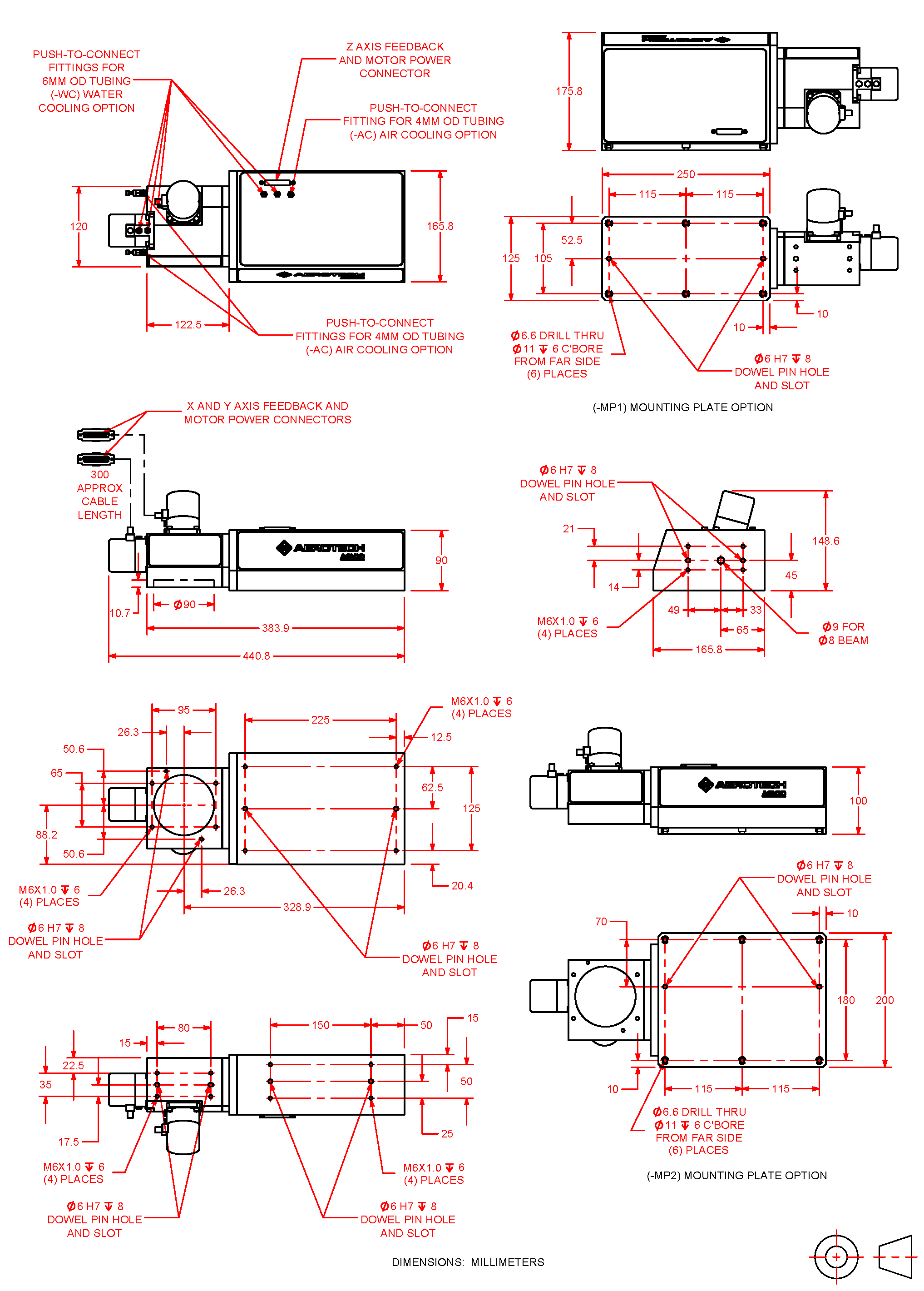
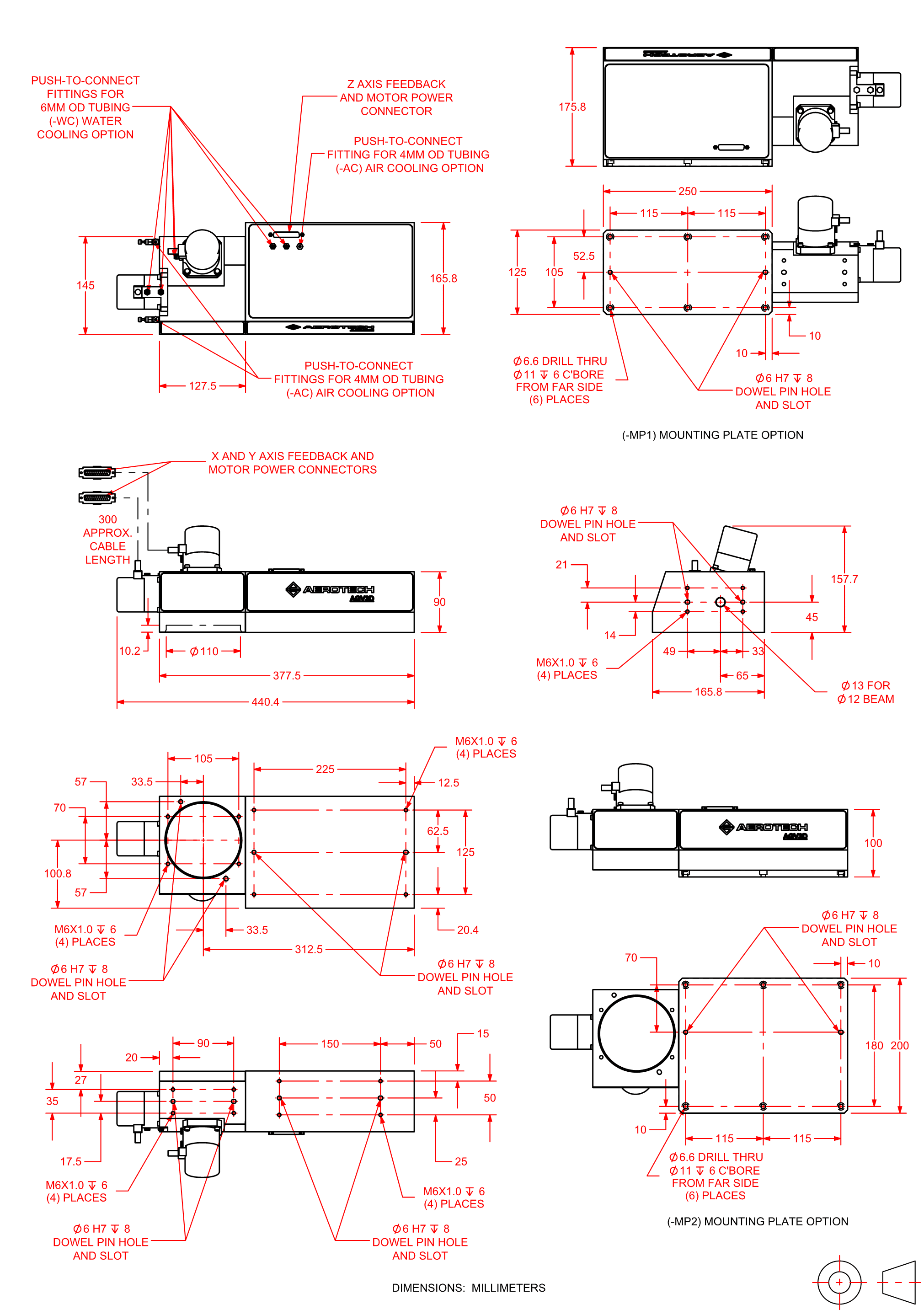
Dimensions
AGV3D-20
AGV3D-30
Ordering Information
Scanner Aperture (Required)
| Option | Description |
| -20 | 20 mm scanner aperture |
| -30 | 30 mm scanner aperture |
Field Configuration (Required)
Field-of-view size is dependent on wavelength. Field configuraton is user-adjustable but must be specified at time of order. See Field Configuration table for details.
| Option | Description |
| -F1 | Near field of view |
| -F2 | Far field of view |
Wavelength (Required)
Contact factory for additonal wavelengths.
| Option | Description |
| -W001 | 10.6 µm |
| -W003 | 1552 nm |
| -W004 | 1064 nm |
| -W005 | 1030 nm |
| -W006 | 532 nm |
| -W007 | 515 nm |
| -W008 | 355 nm |
| -W009 | 343 nm |
| -W012 | 9.3 µm |
Mounting Plate (Optional)
| Option | Description |
| -MP1 | Rear-mounting adapter plate; mounts AGV3D by its rear face |
| -MP2 | Bottom-mounting adapter plate; mounts AGV3D by its bottom face |
Air Cooling (Optional)
| Option | Description |
| -AC | Adds features for air-cooling the galvo scan head and the dynamic focusing module |
Water Cooling (Optional)
| Option | Description |
| -WC | Adds features for water-cooling the galvo scan head and the dynamic focusing module |
Integration (Required)
| Option | Description |
| -TAS | Integration - Test as system
Testing, integration, and documentation of a group of components as a complete system that will be used together (ex: drive, controller, and stage). This includes parameter file generation, system tuning, and documentation of the system configuration. |
| -TAC | Integration - Test as components
Testing and integration of individual items as discrete components that ship together. This is typically used for spare parts, replacement parts, or items that will not be used together. These components may or may not be part of a larger system. |