3D Metrology Systems, Capability Overview, Custom Engineered Motion Systems, Data Storage, Electronics, Gantries, Integrated Automation Systems, Laser Scan Heads, Laser Systems, Medical Device Manufacturing, Motion Control Platforms, Motors, Piezoelectric Nanopositioners, Precision Manufacturing, Process-Specific Products, Semiconductor, Stages & Actuators, Test & Inspection
Capability Overview
Position Synchronized Output (PSO) – Coordinate Part Position with Process Control
Design Features
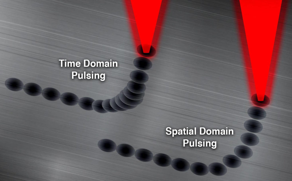
- Trigger your process tool based on distance traveled, avoiding trigger errors based on acceleration, deceleration, or any other velocity instability
- Integrates well with fast-pulsed lasers, enabling next-generation display and medical device manufacturing
- Includes versatile, process-enhancing features
Aerotech’s Position Synchronized Output (PSO) feature coordinates your motion with output that triggers lasers or data acquisition devices for high-speed, high-quality, and unparalleled process control.
Don’t Derive Your Part Quality – Control It
Why control your process based on velocity when you really care about position? Aerotech’s control solutions can fire position-calculated PSO pulses at up to 12.5 MHz and with latencies as low as 40 nanoseconds. You can use these pulses to trigger a laser, sensor, camera, or other devices that accept IO. As processes become more dependent on accuracy and throughput, firing based on actual part position becomes more important. PSO pulses can be commanded on up to three axes of vector motion while tracking the calibrated feedback at high-speeds and low latencies. For kinematic systems, please see this application note on a similar feature, called Part-Speed PSO.
PSO and Laser Processing
Laser technology is constantly evolving, and fast-pulsed lasers are enabling new material processing capabilities. These processes often include the use of fast-pulse or short-pulse lasers. PSO is a differentiating controller feature for these processes because no other control technology allows the sub-micrometer accuracy of laser spot placement without sacrificing throughput. Even at high accelerations, thermal management is possible. Additionally, PSO has long been enjoyed by laser cutting and laser welding applications. These applications include the use of CO2, YAG, and excimer fiber lasers.
PSO is Versatile
PSO’s versatility is defined not only by its low latency and high frequency, but also by the several modes of operation that enable precise integration with many processes. Keep reading to learn more about how PSO works.
PSO Set-Up
Automation1 PSO setup is easy and flexible. Setting up PSO is a matter of setting up component PSO function blocks, each with defined inputs and outputs. Think of setting up these function blocks as a four-step process implemented in Aerotech’s AeroBasic conversational programming language, as illustrated in Figure 2.
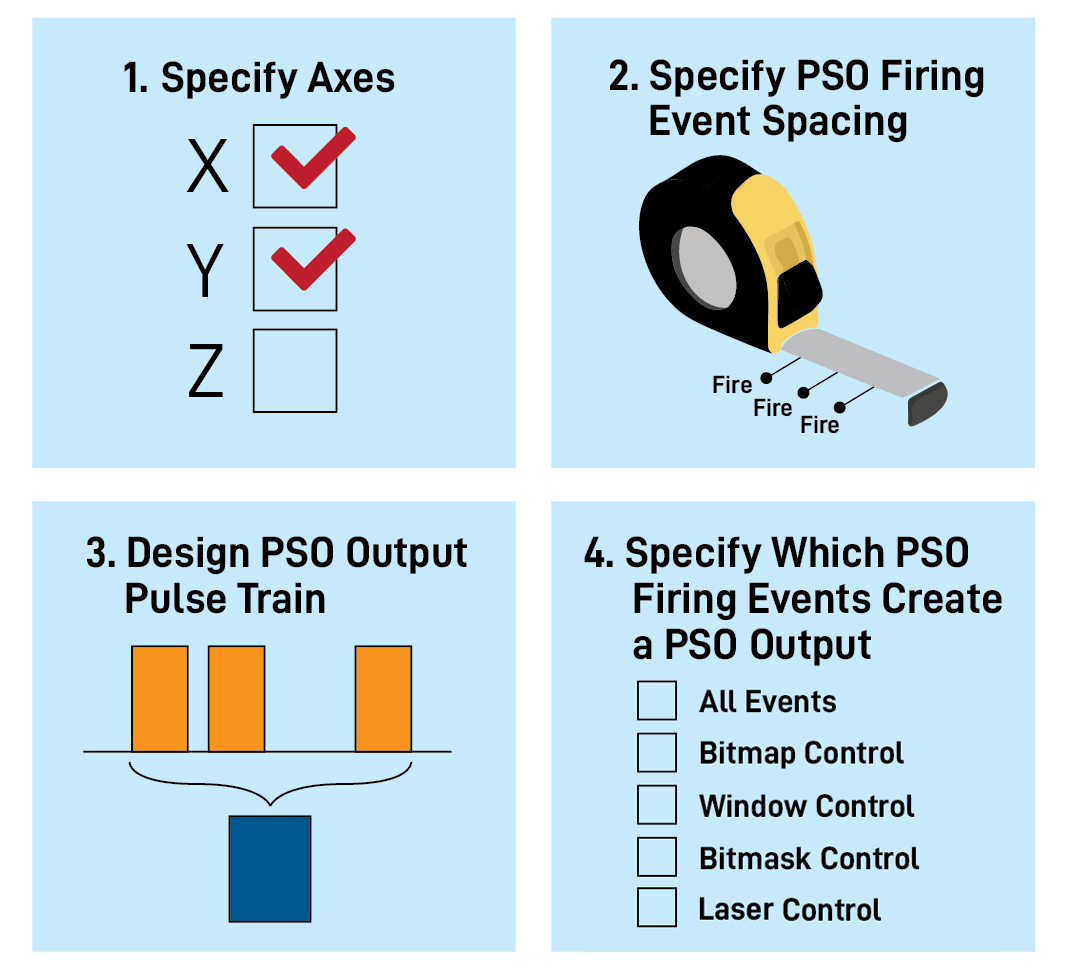
- Specify Axes
- Specify which axes are involved in the vector-based distance.
- Specify the PSO Firing Event Spacing (and Special Firing Event Cases)
- Specify the spacing of the PSO firing event (as well specifying if firing events are generated for entering/exiting specific areas or “windows,” or if a firing event is generated when the Galvo Laser Output turns on). The spacing of PSO firing events can be specified as:
- Fixed distances across a part
- Custom fire-to-fire event distances loaded to a data array
- Specify the spacing of the PSO firing event (as well specifying if firing events are generated for entering/exiting specific areas or “windows,” or if a firing event is generated when the Galvo Laser Output turns on). The spacing of PSO firing events can be specified as:
- Design the PSO Output Pulse Train
- Design the PSO output pulse train required at each firing event. This includes setting up output waveforms, controlling waveform activation and controlling waveform scaling.
- Specify Which PSO Firing Events Create a PSO Output
- A PSO output is generated from physical I/O points on the drive hardware, and can be specified such that a PSO output occurs:
- At All Events: At all PSO firing events
- With Bitmap Control: At PSO firing events except those masked by binary data array values
- With Window Control: Only when the specified axes are within a certain position-based window range
- With Bitmask Control: At all PSO firing events, but the duty-cycle of the PSO output pulse train is modified based on a grayscale array value
- With Laser Control: Only when the laser output turns on
- A PSO output is generated from physical I/O points on the drive hardware, and can be specified such that a PSO output occurs:
Most methods of specifying PSO firing events and PSO outputs can be mixed and matched to optimize your application’s requirements.
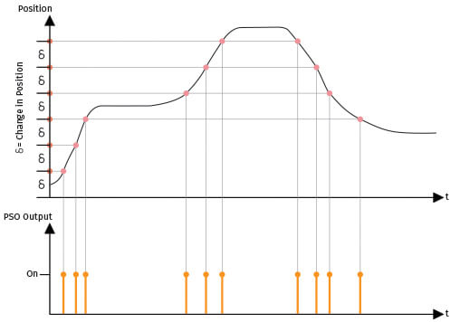
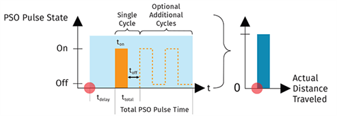
User-Specified PSO Output Pulse Trains
At each PSO firing event, represented by the red dot in each image, a PSO output pulse train is generated but not necessarily output by the drive hardware. When a PSO output pulse is called for, the drive will output the PSO output pulse train as specified. Several cycles can be involved in a pulse train, depending upon your application’s requirements. The amplitude of the PSO output is dependent on the voltage level connected to the PSO circuit. The ability to modify the on/off behavior and amplitude of pulsing makes PSO the most flexible position-based tool command available to high-end, precision processes.
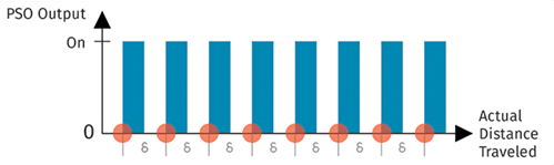
Fixed-Distance Firing
Fixed-Distance PSO pulsing is the most common use case for PSO. This is because firing based on position feedback is the most accurate way to ensure critical process control, such as laser firing or data acquisition, occurs where you intend. In this mode:
- The fixed-distance spacing of firing events is specified by the user.
- Up to three axes of encoder feedback can be used to calculate the actual distance traveled.
- At each PSO firing event, the user-specified PSO output pulse train is generated.
- The PSO output pulse train becomes the PSO output at each PSO firing event.
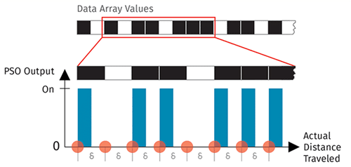
Array-Based, On/Off PSO Output Control
Another common mode for PSO is to specify which fixed-distance PSO firing events create an actual PSO output through the use of data array values. In this mode:
- The fixed-distance spacing of firing events is specified by the user.
- An on/off sequence of desired PSO outputs is created and downloaded to the drive hardware.
- Up to three axes of encoder feedback can be used to calculate the actual distance traveled.
- At each PSO firing event, the user specified PSO output pulse train is generated.
- The PSO output pulse train becomes the PSO output based on the on/off sequence on the drive hardware.
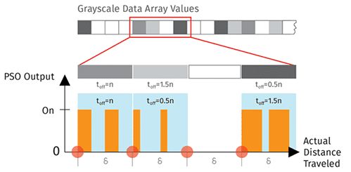
Array-Based Grayscale PSO Output Control
Used for applications such as grayscale laser marking, this PSO mode combines the array-based method above with control of the duty cycle of the PSO output pulse train. In this mode:
- The fixed-distance spacing of firing events is specified by the user.
- An on/off sequence of desired PSO outputs is created and downloaded to the drive hardware. Additionally, each on/off value has a duty-cycle value associated with it, which is also downloaded to the hardware.
- Up to three axes of encoder feedback can be used to calculate the actual distance traveled.
- At each PSO firing event, the user specified PSO output pulse train is generated. The PSO output pulse train becomes the PSO output based on the on/off sequence on the drive hardware.
- The PSO output pulse train is modified based upon the associated duty-cycle value.
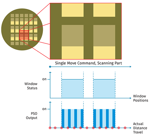
Window-Based PSO Output Control
In addition to on/off and grayscale output control, you can specify position-based windows. Use these windows in applications that require pulsing only take place in certain specified position ranges. The fixed-distance, array-based on/off, and array-based grayscale control are all available in combination with window control. To use window control:
- The user specifies the window range and enables window operation.
- PSO is used as per the above modes.
Custom PSO Pulse Spacing
When implementing any of the above modes, you can use custom PSO firing event-to-event spacing. You can specify custom spacing values for applications where constant spacing is not required.
Control Any Tool and Improve Your Process
Aerotech customers use PSO to trigger processes that include:
- Laser firing
- Camera capture
- Data acquisition
- Nondestructive test triggering
Applications
PSO’s versatility services many noteworthy precision manufacturing processes, including:
- LED-Based Display Manufacturing
- Via Hole Drilling
- Additive Manufacturing
- Printed Electronics/Dispensing
- Laser Systems
- Laser Cutting Stents and Other Interventional Cardiac Devices
- Laser Hermetic Seam Welding of Pacemakers
- Processing of Turbine-Blade Holes
- Fuel Injector Drilling
- Imaging