Application Note, Custom Engineered Motion Systems, Electronics, Gantries, Integrated Automation Systems, Laser Scan Heads, Laser Systems, Medical Device Manufacturing, Motion Control Platforms, Process-Specific Products, Stages & Actuators
Application Note
Synchronizing Position Synchronized Output (PSO) with Mode Locked Lasers
Many lasers are limited to firing pulses based on an internal clock source and cannot be asynchronously triggered from an external signal such as Aerotech’s Position Synchronized Output (PSO) feature. One approach to working with this laser type is to set the pulse width of the PSO output to be the same as the period of the laser clock signal to ensure that the PSO output is active at the laser input sample time (usually the rising or falling edge of the clock). In practice, however, the frequencies of the PSO and laser clock vary based on tolerances of the devices used to synthesize the clock. This variability will result in missed pulses when the PSO output width is shorter than the laser clock period or in extra pulses when the output width is longer than the clock period.
To address this issue Aerotech has added the ability to synchronize the start of the PSO output pulse with the laser clock signal. This capability is supported on the XC6e, iXC6e, XC4e, iXC4e, XC4, iXC4, XL5e, iXL5e, XR3, iXR3, GL4, XL4s, GI4, XI4, and iXI4 Automation1 drives. For these drives, the clock signal is connected to a dedicated PSO External Sync +/- differential input.
The commands required to enable laser clock synchronization functionality are listed below:
PsoWaveformExternalSyncOn()
PsoWaveformExternalSyncOff()
PsoWaveformConfigureDelay()
The PsoWaveformExternalSyncOn command enables the external clock input mode while the PsoWaveformConfigureDelay() function specifies the timing of the output waveform relative to the rising edge of the laser clock. The PsoWaveformConfigureDelay() function is optional. Using this feature will result in a decrease in the positional accuracy of the spot placement as the PSO output signal is delayed until the next rising edge of the laser clock. The maximum decrease in spot placement accuracy is proportional to the linear speed of the axes (in units/second) multiplied by the summation of the laser clock period and the configured delay in seconds. For example, assume the programmed speed is 100 mm/s, the clock frequency is 200 kHz and the DelayTime is 2.5 µs. The maximum pulse placement error would be calculated as follows:
100 mm/s • (1/200000 + 0.0000025) = 100 mm/s • (0.0000075) = 0.75 µm
Pulse placement accuracy will vary from a minimum defined by the DelayTime setting to a maximum value calculated from the combined DelayTime and clock period (as shown above).
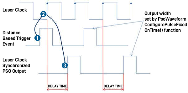
Figure 1 shows the timing of the PSO output pulse relative to the laser clock along with the effect of the DelayTime setting.
If multiple output pulses are required, the PsoWaveformConfigurePulseFixedOnTime() function $onTime argument should be increased to span multiple laser clock sampling events.
Summary
By using the PsoWaveformExternalSyncOn() function it is possible to synchronize the PSO output on several Automation1 drives with an external clock source. The user should be aware of the impact on spot placement accuracy due to the delay in the laser output relative to the desired firing location. Finally, the clock source from the laser may need to be modified to support the input specifications of the connected drive (consult the appropriate drive hardware manual).