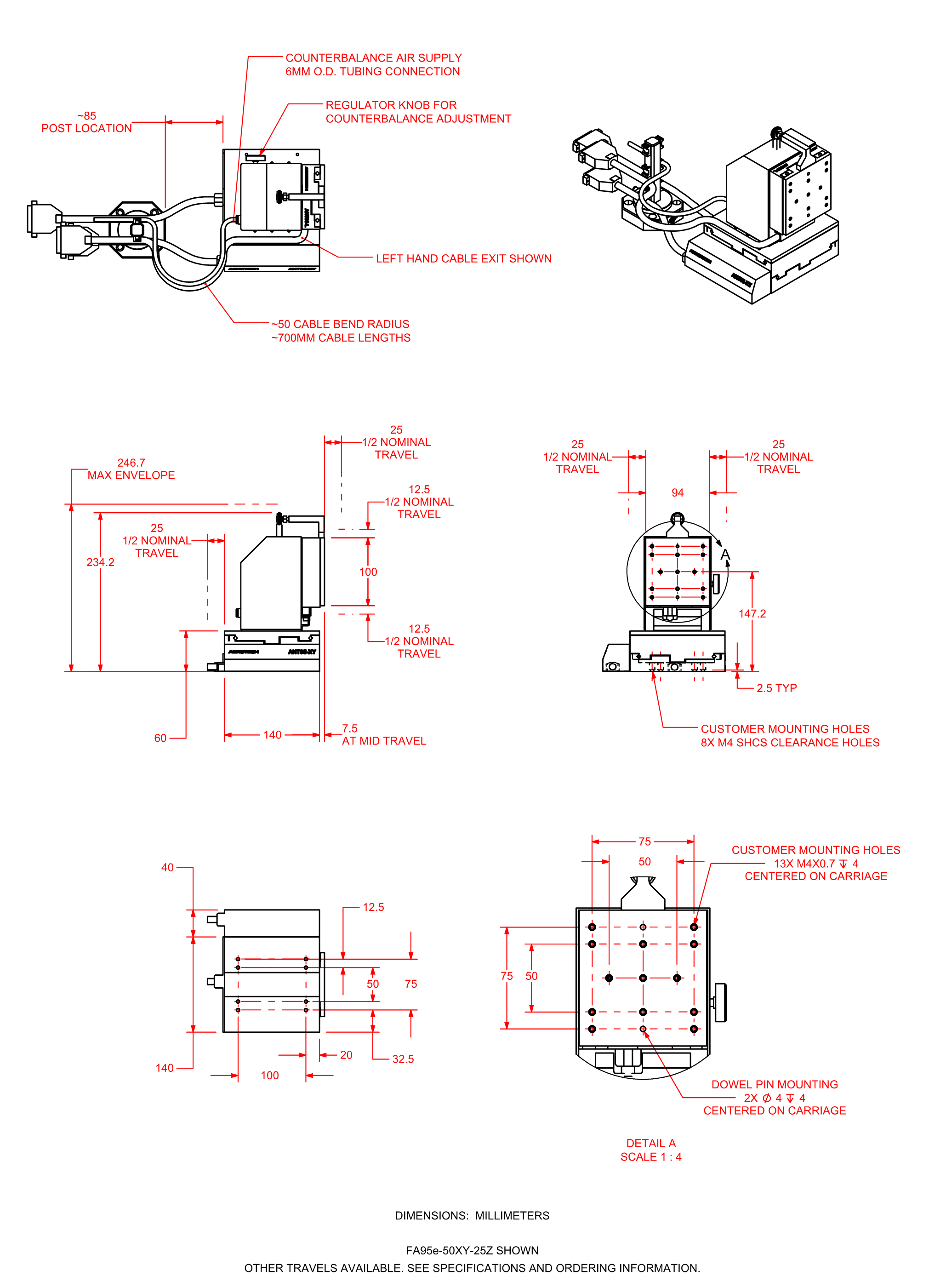
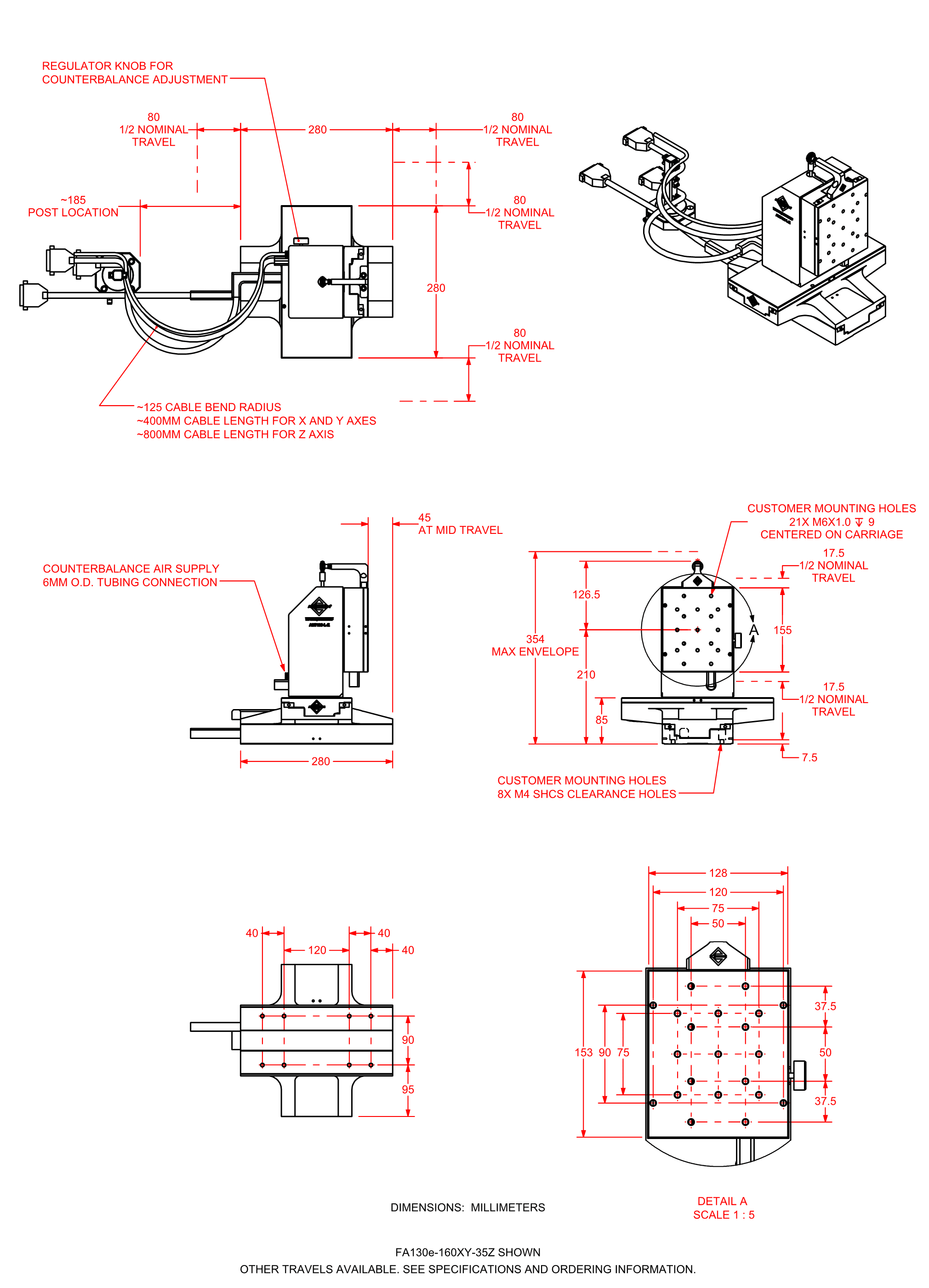
FiberAlign FA95e and FA130e Series Direct-Drive, Multi-Axis Photonics Alignment System
The enhanced FiberAlign™ FAe series is a high-performance photonics aligning system incorporating best-in-class drive and state-of-the-art axis control technology. The FAe series delivers superb accuracy and minimum step sizes. Modular design permits the selection of the number of axes, travel distance and load capacity to exactly fit the application, all while maintaining high speed, resolution and accuracy.
Description
Specifications
Dimensions
Ordering Info
Downloads
Description
Description
Specifications
Dimensions
Ordering Info
Downloads
Description
Design Features
- 3- to 6-axis photonics alignment
- High resolution (2 nm), repeatability (100 nm), and accuracy (300 nm)
- Anti-creep crossed-roller bearings
- Noncontact direct-drive linear motors
- Direct-drive rotary and goniometer options
- Raster, spiral, or power peaking algorithms
- Interface to industry-standard power meters
Automated Production
As alignment accuracies, the quest for higher yields, and device volumes increase, the need for a precise, reliable, and repeatable motion system becomes increasingly important. Due to the rapidly changing nature of components and manufacturing processes, flexibility in system configuration becomes a must. Aerotech’s FAe series responds to and satisfies all of these requirements. With the selection of robust system components and decades of precision motion experience, high-volume production in a 24/7 manufacturing environment has become a reality.
Advanced Drive Technology
Only noncontact direct-drive technology offers the robust, accurate, high-speed, and high-resolution positioning necessary for mass production of precision devices. Aerotech's state-of-the-art drive technology offers industry-leading resolution combined with travels up to 160 mm and positioning speeds up to 200 mm/s. Utilizing ultra-quiet linear drives and advanced control technology, Aerotech’s FAe series offers the best position repeatability, accuracy, and in-position stability to meet the motion system requirement of higher yields.
Fast Vision Alignment and Power Scanning Algorithms
A comprehensive software toolkit provides easy access to commonly used functions. Alignment functions such as hill climbing from a power meter input, and raster, square, or circular spiral scans are easily implemented via standard functions. In addition to the automated tools, both joystick and on-screen jog control are available for manual operations.
FA95e or FA130e - Which is Right for You?
To satisfy the ongoing positioning and processing needs of the photonics manufacturing industry, Aerotech offers both the FA95e and FA130e. Both basic three-axis models can be extended with additional axes to satisfy the requirement to control motion in six axes: X, Y, Z, T (yaw), P (pitch), R (roll).
FA95e represents the more compact version (one-third of the volume of FA130e) and is ideal where space is limited. Additional axes can be attached to provide high-resolution, high-accuracy rotary motion.
Yaw rotary motion is provided by Aerotech’s ANT95-R direct-drive, high-resolution rotary actuators, while pitch and roll motion are provided by Aerotech’s advanced ANT-20G series direct-drive, high-resolution goniometers. The rotary devices offer a 20 degree angular range with industry-leading step resolution of 0.01 arc-seconds.
The FA130e is similar in construction to the FA95e but offers a larger travel and larger load carrying capability in a slightly larger envelope. Travel for the X and Y axes are selectable up to 160 millimeters.
The FA130e also accepts the ANT95-R rotary actuator and the ANT-20G goniometers, providing up to six axes of motion control.
Ordering Information
FA95e Direct-Drive, Multi-Axis Photonics Alignment System
| Option | Description |
| FA95e | Proprietary direct-drive motor technology, linear-encoder-based fiber translator; XYZ axes aligned to 10 arc-sec orthogonal |
XY Axis
| Option | Description |
| -25XY | 25 mm x 25 mm XY travel |
| -50XY | 50 mm x 50 mm XY travel |
Z Axis
| Option | Description |
| -25Z | 25 mm Z travel |
Z-Axis Cable Exit
| Option | Description |
| -RH | Z-axis right-hand cable exit |
| -LH | Z-axis left-hand cable exit |
Optional Rotary Axes
The axis orientation is X,Y,Z working from the bottom to the top axis. X is bottom axis, Y is middle axis, and Z is the top (vertical) axis.
| Option | Description |
| -A | XY cable exits in the rear; vertical axis tabletop parallel to middle-axis (Y) facing to the front |
| -B | XY cable exits in the rear; vertical axis tabletop parallel to bottom-axis (X) facing to the left |
| -C | XY cable exits in the rear; vertical axis tabletop parallel to bottom-axis (X) facing to the right |
Optional Accuracy Grade
| Option | Description |
| -PLUS | High-accuracy version |
FA130e Direct-Drive, Multi-Axis Photonics Alignment System
| Option | Description |
| FA130e | Proprietary direct-drive motor technology, linear-encoder-based fiber translator; XYZ axes aligned to 10 arc-sec orthogonal |
XY Axis
| Option | Description |
| -60XY | 60 mm x 60 mm XY travel |
| -110XY | 110 mm x 100 mm XY travel |
| -160XY | 160 mm x 160 mm XY travel |
Z Axis
| Option | Description |
| -35Z | 35 mm Z travel |
| -60Z | 60 mm Z travel |
Optional Rotary Axes
The axis orientation is X,Y,Z working from the bottom to the top axis. X is bottom axis, Y is middle axis, and Z is the top (vertical) axis
| Option | Description |
| -T | Single rotary-axis oriented as yaw; rotation about Y-axis (ANT95-20-R) |
| -P | Single goniometer rotary-axis oriented as pitch; rotation about Y-axis (ANT-20G) |
| -R | Single goniometer rotary-axis oriented as roll; rotation about X-axis (ANT-20G) |
- Other axis combinations available upon request.
Axis Orientation
The letters in the axis orientation correspond to the standard XYZ configurations detailed in Aerotech's multi-axis assembly specification. The letter indicates the orientation of the vertical axis (Z) relative to the bottom axis (X).
| Option | Description |
| -A | XY cable exits in the rear; vertical axis tabletop parallel to middle-axis (Y) facing to the front |
| -B | XY cable exits in the rear; vertical axis tabletop parallel to bottom-axis (X) facing to the left |
| -C | XY cable exits in the rear; vertical axis tabletop parallel to bottom-axis (X) facing to the right |
Optional Accuracy Grade
| Option | Description |
| -PLUS | High-accuracy version |


