AeroScriptPlus Advanced Controller Functionality
With the AeroScriptPlus feature, available in your Automation1-iSMC controller configuration, you can run any AeroScriptPlus program— including AeroscriptPlus DrillOptimizer, AeroAlign Optical Alignment Algorithms and Tool Center Point programming system configuration—on your controller. You can access AeroScriptPlus features through the AeroScript programming language in Automation1 Studio or through the Automation1 .NET, Python, and C APIs.
AeroScriptPlus programs are specially designed AeroScript library files that you can purchase via the AeroScriptPlus product configurator. Each AeroScriptPlus program supplies special canned functionality for specific systems and applications. These files are encrypted and can only be run on Automation1 controllers that have AeroScriptPlus configured.
More AeroScriptPlus programs are coming soon to Automation1, and capabilities will continuously improve.
Description
Specifications
Ordering Info
Downloads
Description
Description
Specifications
Ordering Info
Downloads
Description
Design Features
- Optimizes laser drilling
- Solves complex problems such as optical alignments and tool center point programming
- Enables AeroScriptPlus functionality on each controller you deploy
- Runs multiple AeroScriptPlus programs simultaneously with a single license
- Includes complex application specific programming that is ready for use
Automation1
The Automation1 AeroScriptPlus feature is part of the user-friendly Automation1 motion control platform, which includes the following:
AeroAlign Optical Alignment Algorithms
The AeroAlign Optical Alignment Algorithms execute searches to align power signals for fiber optic, photonic and optical devices. Optical alignment is typically a two-step process: detecting initial power, or finding first light, followed by power optimization. While alignment optimization algorithms not designed to find first light require an initial power signal, algorithms designed to find first light do not. Some algorithms can perform both first light alignment and power optimization. The appropriate algorithm (or combination of algorithms) for your process depends on your application’s parameters.
Tool Center Point Programming
Tool Center Point Programming (TCP) allows you to create motion programs in part coordinates that are independent of the physical machine configuration. TCP is easily accomplished for 3-axis linear Cartesian X/Y/Z systems, as the position of the tool in part space has a fixed offset relative to the machine axes.
When one or more rotary axes are present, the calculation becomes more complex because there is no longer a fixed relationship between part and machine coordinates. The calculation of machine coordinates from part coordinates requires the application of a rotation matrix.
Automation1 is capable of transforming part coordinates into machine coordinates in real time for actuators with up to six degrees of freedom (three linear, three rotary).
Laser Drilling Optimization
AeroscriptPLUS DrillOptimizer enables profile-specific optimization of motion path and motion parameters for drilling thousands to millions of vias. Use it to achieve production-scale performance for Aerotech’s AGV galvo laser scan head products (AGV-HPO and AGV-XPO) with minimal setup time. DrillOptimizer provides a two-step process: first, it optimizes the shortest path for the galvo laser scan head to follow and then it optimizes the drive and laser scan head motors to make 100% of the moves within your specific quality criteria. DrillOptimizer is available as a standalone user interface through Automation1 Studio or as a .NET DLL, making it easy to integrate it directly into your machine HMI.
Name |
Function |
Description |
|
| AeroAlign1D | 1D First Light or Peak-Finding | The AeroAlign1D function is used to search along one degree of freedom for a local power peak or a defined power threshold. This algorithm can perform a complete scan of a defined 1D area and return to the point of maximum (or minimum) power, or it can be configured to terminate motion and remain in place upon reaching a user-defined power threshold. |  |
| AeroAlignSpiral | 2D First Light or Peak-Finding | The AeroAlignSpiral function is used to search along two degrees of freedom for a local power peak or a defined power threshold. This algorithm can perform a complete scan of a defined circular 2D area and return to the point of maximum (or minimum) power, or it can be configured to terminate motion and remain in place upon reaching a user-defined power threshold. |  |
| AeroAlignDynamic | 2D Peak-Finding | The AeroAlignDynamic function is used in one of two ways: it can optimize the position of two degrees of freedom to find a power peak, or it can dynamically track the position of an existing peak. After first light is identified, AeroAlignDynamic climbs a local power peak and then can either stop when a user-defined threshold is reached or continue to track the movement of that peak until the end of a user-defined time period. |  |
| AeroAlignFast | Multi-Dimensional Peak-Finding | The AeroAlignFast function uses an iterative search routine to identify a position where the power signal exceeds a user-defined threshold. This algorithm supports up to six degrees of freedom and can be used in a wide range of kinematic configurations, including across multiple alignment platforms. |  |
Topic |
Description |
|
| TCP Machine Tool Standards |
Standards exist in the machine tool industry for associating linear and rotary axes and defining positive move directions of all axes. Adhering to these standards removes uncertainty when anticipating how machine axes will move in response to motion commanded in part space. The positive move directions and the orientation of the axes in the Part coordinate system are defined per the right hand rule as shown to the right. The left hand image is for positive linear convention and the right hand image is for positive angular convention. |
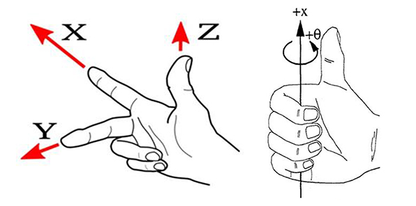 |
| TCP Machine Tool Standards | Rotation occurs about a part linear axis per the relationship shown in the figure to the right. When TCP is active, the A axis rotates the tool center point about the part X axis, the B axis rotates the tool center point about the part Y axis and the C axis rotates the tool center point about the Z axis. |
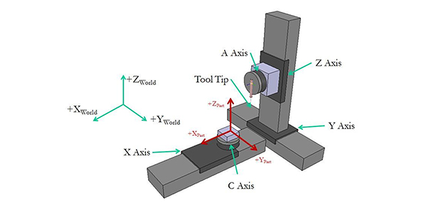 |
| Machine Configuration | To perform TCP kinematic calculations, the controller must know the locations of the tool, part and rotary axes and the configuration of the rotary axes. Offset Position Configuration A common approach to establishing machine configuration is to specify offsets between the points of rotation of the rotary axes and the location of the tool and the part. This configuration mode accommodates the input of coordinates based on their distances from the Part or Tool Tip they are connected to. Absolute Position Configuration Another common approach is using the absolute positions of all system elements based on their location in a “World” coordinate frame. |
|
| Acceleration Limiting | The CoordinatedAccelLimit parameter will stop or slow down path velocity for non-tangent linear moves. The DependentCoordinatedAccelLimit parameter will stop or slow down program velocity for non-tangent rotary axis moves. Note: The effect of changing speed on the machining process may prevent the use of Acceleration limiting in applications which require constant surface speed. |
|
| Commanded Velocity Filtering |
A low pass IIR filter (TrajectoryIIRFilter) or moving average FIR filter (TrajectoryFIRFilter) can be applied to the velocity command of the virtual and/or physical axes. The filter is applied continuously and will modify the program path by rounding all of the transitions between moves, even those that do not exhibit large accelerations. The positions of the linear servo axes are calculated from the virtual x/y/z axes and the servo rotary axis commanded positions. Similar filter settings should be applied to both virtual x/y/z and physical A/B/C axes to ensure consistent phasing of commanded position used to calculate the servo X/Y/Z positions. Note: Applying a filter to the servo rotary A/B/C axes and servo X/Y/Z axes will cause the servo X/Y/Z axes to lag behind the servo rotary axis position command. |
|
| Path Optimization | Lead on/lead off moves or “skywriting” is commonly used in X/Y applications to ensure the tool is only engaged in the material at constant speed. The calculation of lead moves or skywriting sequences is more complex on 3D shapes as the inserted path geometry cannot cause a collision between the part and the tool. Normally the process consists of a lead-off and lead-on move inserted between two nontangent features. The tool is turned off before the lead-off at constant surface speed. The path velocity decelerates to 0 during the lead off move. The controller moves to the start of the lead-on move, which is tangent to the next path segment and the system reaches constant speed during the lead-on move and enable the tool at the end of the lead-on move. |
Name |
Function |
Description |
|
| Path Optimization | Profile-Specific Path Optimization | Organize >1,000,000 drill locations with the shortest path distance in seconds. Organize for single FOV or with IFOV. | 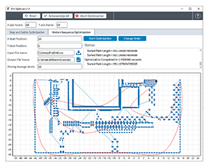 |
| Motion Optimization | Drive & Motor Parameter Optimization | Optimize AGV laser scan head hardware to execute 100% of moves at maximum performance within the user-defined settle window. Eliminate any delay for laser trigger and motion settle. | 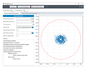 |
| Execution Framework | OptimalRapid Library & Program Execution | OptimalRapid is an AeroscriptPlus library that uses Path Optimization and Motion Optimization outputs to execute the list of points using a small, lightweight program that enables rapid iteration of different motion profiles and optimized parameters. Use it to iterate and obtain production scale performance quickly. | 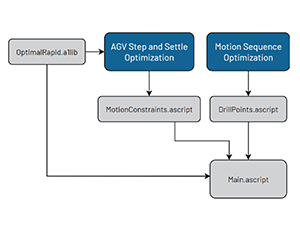 |
| API | .NET Dll | DrillOptimizer includes a Windows .exe for performing Path Optimization and Motion Optimization, plus a .NET Dll so machine builders can integrate its functionality into their custom machine HMI. |  |
Dimensions
Ordering Information
Filetype
| Option |
| Compiled AeroScript Library File |
File
| Option | Description |
| -F1 | Optical Alignment Algorithms, Compiled AeroScript Library File |
| -F2 | Tool Center Point Programming, Compiled AeroScript Library File |
| -F3 | Drill Optimizer, Windows Application, API & Compiled AeroScript Library File |
- To load and run AeroScriptPlus files on your controller, your Automation1-iSMC motion controller must be configured with the -AP1 option.