Aerospace & Defense, Capability Overview, Electronics, Gantries, Integrated Automation Systems, Laser Scan Heads, Laser Systems, Medical Device Manufacturing, Motion Control Platforms, Process-Specific Products, Stages & Actuators
Capability Overview
Advanced Laser Controls – Features to Improve Your Process
Untangle Your Parameters for Consistent, High-Quality Processing
Eliminating laser processing parameters’ dependency on motion trajectories generates more consistent laser-material interaction and improves part yields. Aerotech’s patented laser control features allow users to untangle the process parameters forcing critical design compromises in many laser machining centers. Aerotech’s Automation1 PC-based motion controller enables a single controller architecture for galvanometer-based laser scan heads and traditional linear/rotary servo control with laser processes. Automation1 contains powerful features for combining these motion types with calibrated laser triggering for position and power density. This means a process can be consistent and reproducible without any dependency on process speed or scanner field of view (FOV).
Infinite Field of View

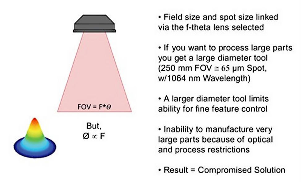
Aerotech’s Infinite Field of View (IFOV) controller feature improves laser machining systems’ throughput, quality and precision. With IFOV, there are no limits on a laser scanner-based system’s working area. This allows for using optimized optical components to minimize spot size and keep the working area flexible. In most contemporary laser processing systems with a galvo scan head, the field size and focused spot diameter are connected through the f-theta lens selection. If users want a large field size to process larger parts and improve throughput, they have to compromise with a larger spot size. A larger spot size can hinder the ability to make quality cuts or fine features. If the process demands a small spot size, users are limited to a small working area and cannot achieve high-throughput. IFOV eliminates these constraints, so users don’t have to settle for a compromised solution.
Position Synchronized Output
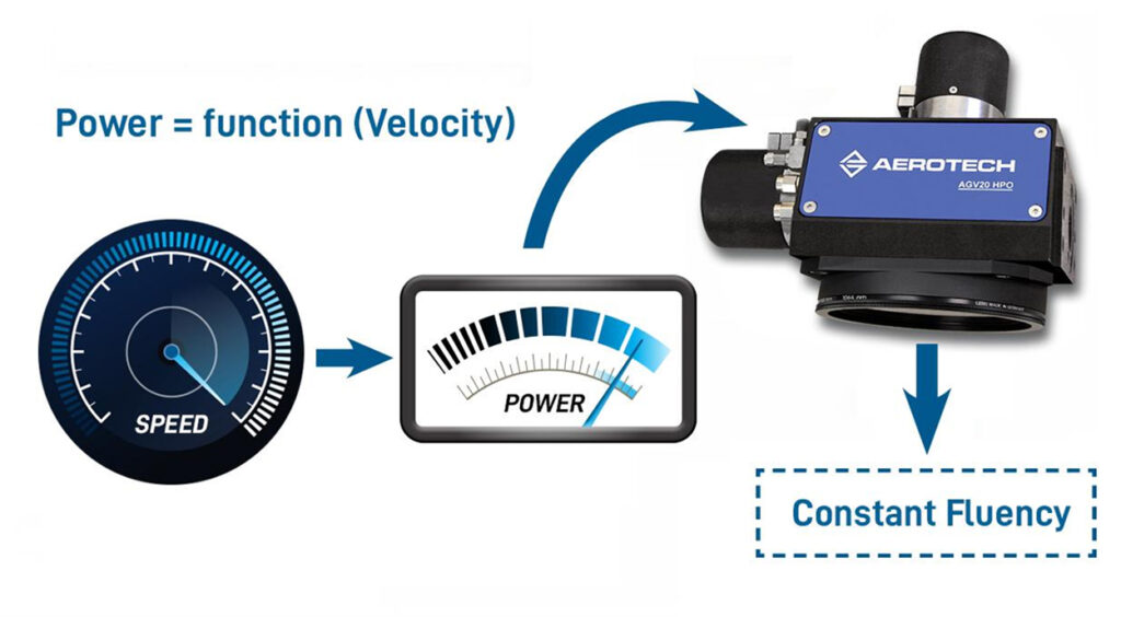
Aerotech’s Position Synchronized Output (PSO) feature controls laser delivery in the spatial domain, allowing for pulse rate modulation as a function of the true tool-on-part velocity and laser spot position. This alleviates process parameter entanglement that would result from the laser control system’s interaction with the motion subsystem.
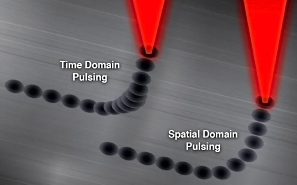
Most modern laser systems can trigger at rates between several 100 kHz to several MHz, which is commonly referred to as the laser’s repetition rate. These rates are constant but allow for an external trigger signal (such as PSO) to dictate when the laser pulse is commanded. In many control solutions that implement a scanner only or a scanner with linear/rotary servo motion, the trigger command comes from time domain spacing alone. PSO leverages the scanner axis and linear/rotary servo axis digital encoder feedback to trigger the laser in real time based on the beam’s calibrated position on the working surface or at the work point.
Using PSO keeps spot overlap consistent throughout the motion profile, regardless of which axis is contributing to the beam’s velocity at any given point on its intended path. This stabilizes the laser fluence (or energy/unit area) along the path and allows the motion system to speed up and slow down without any inconsistencies. As a result, applications can take full advantage of the laser scan head’s dynamic performance capabilities without suffering dynamic accuracy losses. Constant and programmably variable spot overlap via PSO gives users explicit control of laser energy density delivered to the part independent of the system dynamics, enabling better process quality control. In addition to throttling the motion system from its full capability, traditional laser control that demands constant velocity makes the programming and motion path more complex. A constant velocity constraint often adds length to the overall motion path via splines added to fine features, again reducing throughput.
Power Correction Mapping
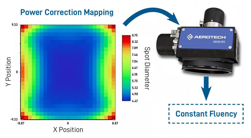
Power correction mapping ensures high-quality material processing and enables higher throughput. As discussed in the IFOV and PSO sections, quality cutting of many modern materials is very sensitive to fluency. Users want to take advantage of their laser delivery system’s entire available working area, as long as doing so doesn’t degrade quality. Even in scanner-based systems using IFOV, using the full working area of the scanner increases system throughput because it allows the scanner to do the most work during combined motion. Many optical systems, especially field flattening optics, cause spot distortion throughout the field – particularly when approaching the edges. Aerotech’s Automation1 controller allows for the creation of power correction maps to account for the distortion of the laser spot as a function of position in the field. As the system moves through travel, the controller automatically manages the laser source’s power output through analog outputs to maintain a more constant fluency at the part. This results in better quality control.
Power Throttling
Power throttling is another tool that ensures users achieve the highest processing quality and consistency. As the power mapping function modulates laser power as a function of position, the Automation1 controller allows the user to automatically scale the power output as a function of combined vector velocity of the laser spot. The faster the laser spot moves, the more power required to maintain average fluency across the cutting path. Power throttling is achieved through Analog Vector Tracking, which works jointly with PSO and Power Mapping to take all aspects of the motion into account during laser control. Like PSO, IFOV and Power Mapping, this tool gives users maximum control over their process parameters without demanding any compromises.